Installing the Cabinet with Earthquake Bracing
|
17/BYB 501/1 (2 x SXK 118 0168/1) Earthquake Set, Concrete Floor |
|||
|---|---|---|---|
|
Pos. |
Title/Function |
Product Number |
Quantity |
|
A |
FIXING IRON |
SXA 123 0380/1 |
4 |
|
B |
BAR |
SXA 123 0381/1 |
2 |
|
C |
COASTER |
SXA 123 0382/1 |
4 |
|
D |
EXPANDER SCREW M 12/25 |
NSV 907 02 |
4 |
|
E |
INSULATING BUSHING |
SXA 106 0093/2 |
4 |
|
F |
WASHER |
SCA 118 210/78 |
4 |
|
G |
WASHER |
SCA 118 170/78 |
4 |
|
H |
SCREW M 16X25 |
03/SBA 186 160/0250 |
4 |

The following procedure must be performed for the feet at the front and for the feet at the back:
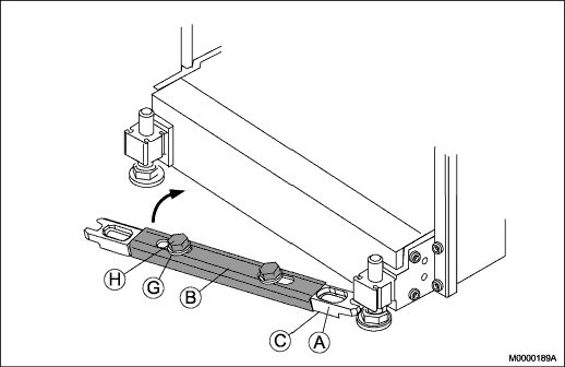
- Slide the earthquake bracing under the cabinet between the feet, see Figure 1.
- Verify that two coasters (C) are installed under the two fixing irons (A).
- Install the two fixing irons (A) between the feet of the cabinet with the bar (B), two screws (H), and two washers (G).
- Align the holes in the fixing irons over the anchoring holes in the floor.
- Tighten the two screws (H) to a torque of 80 Nm.
Anchoring the Cabinet on a Concrete Floor


The following procedure must be performed for the feet at the front and for the feet at the back:
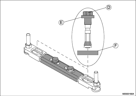
- Place two expander screws (D) with insulation bushing (E) and washer (F) through the fixing irons and into the concrete floor, see Figure 2.
- Hammer the two expander screws into position.
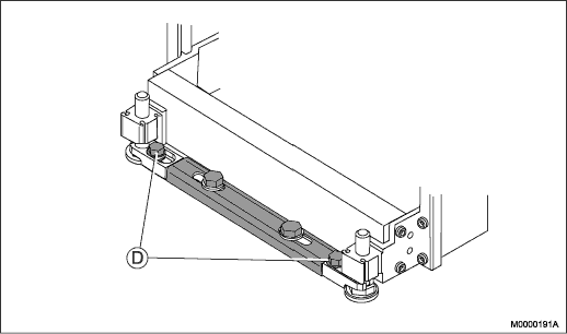
- Secure the two expander screws and earthquake bracing by tightening the screws until the red caps snaps off, see Figure 3.Note:
The red cap snaps off when the screw has been tightened to the proper torque, exposing a green washer. The green washer should be intact, with no breaks. If the washer is found damaged during inspection, the screw must be verified to have a minimum torque of 64 Nm (but not exceeding 68 Nm).
Proceed to the next installation stage, see Fastening the Cabinets.