Fan Unit Alarm
Fan BFD 509 08/4
Connect the fan alarm cable TSR902 0274/2200 to the D-sub connector on the Fan, and connect the other end to the MDF; see the following figure.
Connect the Plug, SXK 106 2097/1 in the second D-sub connector on the Fan, to receive a signal loop.
Connect the ALU2 board to the MDF according to the cabling list for the site. Use cable TSR 491 0306 or similar. For an example of connection to the ALU2 board, see the following figure.
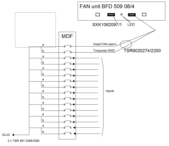
The Fan unit BFD 509 08/4 has the following alarm indicators:
Yellow LED
The yellow LED is blinking when the Alarm is activated. The Alarm can be activated either by heat or lost of one of the -48V feeding.
Fan alarm_A is active when one or more of the conditions is/are:
-48Va or -48Vb input is too low (towards 0 V) or
the temperature is above 55 degrees C or
the temp.sensor fails (out of range) or
the FAN motor current is out of range or
the FAN or motor voltage regulation fail