IP Signaling Security
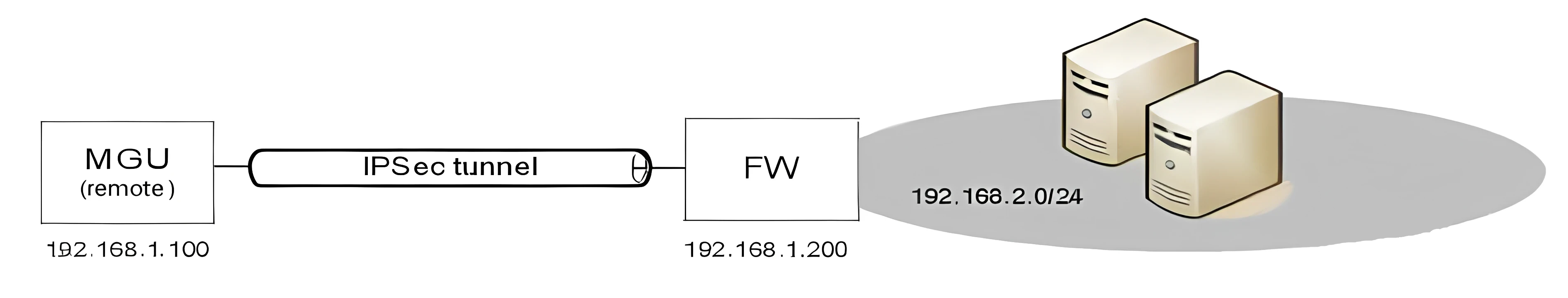
MGU supports Internet Protocol Security (IPsec) that can be used to secure IP communication between MGU and a remote IPsec peer (a remote Service Node or Gateway/ Firewall). For example, IPsec may be used in a branch node scenario where Service Nodes are located in a head office and MGUs in branch offices while signaling over the Internet. IPsec is supported for MGU signaling over IPv4 networks.
The IPsec protocol suite is an open standard described in RFC 2401. IPsec is based on the following protocols:
- Authentication Header (AH) to provide connectionless integrity, data origin authentication, and an optional anti-replay service.
- Encapsulating Security Payload (ESP) to provide confidentiality (encryption), and limited traffic flow confidentiality. It also may provide connectionless integrity, data origin authentication, and an anti-replay service.
- Internet Key Exchange protocol (IKE) to provide automatic establishing of Security Associations (SA) and peer authentication. MGU supports IKE version 1 (IKEv1). IKE is only used in automatic key management procedures.
AH and ESP may be used in combination, but usually only one of them is used. When only ESP is used it is usually in combination with authentication. By default MGU enables ESP with authentication. Most importantly, ESP will protect the confidentiality of the SRTP keys exchanged between Service Node and MGU for secure RTP. For some installations it might make sense to only use AH.
IPsec may be used in tunnel (a.k.a VPN tunnel) or transport mode. In tunnel mode, the entire IP packet is protected by IPsec. This means IPsec wraps the original packet, encrypts it, adds a new IP header and sends it to the IPsec peer. In transport mode, only the IP payload is protected by IPsec. Tunnel mode is usually used between networks or host-to-networks, and transport mode is usually used end-to-end between two hosts. MGU creates a transport if a destination address is specified or a tunnel if destination network is specified.
MGU allows automatic IPsec SA establishment and peer authentication through IKE/ISAKMP using either pre-shared keys or RSA signed digital certificates. It is also possible to use manually configured SAs, but is usually not recommended.
It is possible to setup multiple IPsec tunnels/transports between MGU and remote peers.
For more information about how to setup IPsec, see Operational Directions MGU SECURITY CONFIGURATION.
Visual Indications
There are a few LEDs on the MGU front showing operational status of the board and interfaces. There is the main Status LED and additional LEDs on each Ethernet and E1/T1 port.
Status LED
The Status LED on MGU shows general operating status as follows:
- Flashing red - The board is in boot loader mode.
- Steady red - The board is not active.
- Steady green - The board is activated (connection with MX-ONE Service Node established on all three communication ports).
- Flashing green - The board is activated, and signaling packets (SCTP) are transmitted between MX-ONE Service Node and MGU.
Ethernet LEDs
- Green LED - Shows flashing green when ethernet packets are sent or received
- Yellow LED - Shows steady yellow when 100Mbit
E1/T1 LEDs
- Green LED - Shows steady green when layer 1 is activated and there is incoming frame synch. Flashes when there is layer 2 activity, i.e. HDLC data frames are sent or received.
- Yellow LED - Shows steady yellow if the link is PCM syncronization source.
Alarm Handling
Each alarm type has a unique number and an alarm text which is sent in a status message to MX-ONE Service Node. Alarms are also logged in the MGU's syslog at ./var/log/syslog in MGU's file system.
The alarm table below enumerates all alarms that can be generated from the MGU board, with their alarm number and severity. These alarms belongs to the Media GW alarm domain (5) in MX-ONE Service Node.
The following table lists the Media Gateway alarms and Alarm encodings. All Media Gateway alarms belongs to "alarm domain" 5 in Telephony System.
Encoding *) |
Alarm description |
Severity |
|
Code |
ID |
||
9 |
9 |
Power Problem: -5V failure in backplane |
Critical |
9 |
10 |
Power Problem: +5V failure in backplane |
Critical |
9 |
11 |
Power Problem: -12V failure in backplane |
Critical |
9 |
12 |
Power Problem: +12V failure in backplane |
Critical |
18 |
18 |
Equipment Malfunction: External alarm A raised **) |
Indetermined |
19 |
19 |
Equipment Malfunction: External alarm B raised ***) |
Indetermined |
20 |
20 |
LAN Error Lost connection to LAN 0 |
Warning |
20 |
21 |
LAN Error Lost connection to LAN 1 |
Warning |
22 |
22 |
LAN Error: LAN0 Gateway unreachable |
Warning |
22 |
23 |
LAN Error: LAN1 Gateway unreachable |
Warning |
24 |
24 |
VLAN Error: VLANs with same GW MAC ADDR |
Warning |
34 |
26 |
MGU Resource Warning: High load in DSP core inside MSP |
Warning |
34 |
27 |
MGU Resource Warning: High load in ARM core inside MSP |
Warning |
34 |
28 |
MGU Resource Warning: No more time slots available |
Minor |
34 |
29 |
MGU Resource Warning: MSP out of resources |
Minor |
*) |
In Telephony System's alarm log, only the alarm code (and domain) is logged (e.g. 5 and 22 for LAN Error). In MGU's syslog, only the alarm Id is logged, as for example: "AlarmSupervisor-raiseAlarm for id = 23 MO = MGW" indicating LAN1 Gateway unreachable. |
**) |
The alarm definition (alarm code and alarm text) is configurable from MX-ONE Service Node to describe actual alarm source. |
***) |
The alarm definition (alarm code and alarm text) is configurable from MX-ONE Service Node to describe actual alarm source. |