Digital Trunk E1/T1 Interface
MGU provides 8 digital trunk interfaces (PRI:s) of type E1 orT1. Each PRI is implemented as a “virtual board” in the “virtual magazine 2” (i.e. EQU range 2-0-00 to 2-70-31) and can be configured and run independently of each other.
- E1 with ISDN protocol (corresponding to a TLU76/11 board)
- E1 with CAS protocol (corresponds to a TLU76/13 board)
- T1 with ISDN protocol (corresponding to a TLU77/11 board)
MGU ISDN/PRI interface has been verified to comply with ETSI TBR004 (EU), TIA-968-A 47 CFR Part 68 (US), CS-03 Issue 9 Part VI (CA), AS/ACIF S038 (AU) and Newsletter No 125 (NZ).
MGU's Layer 1 and 2 supports ETS 300 011 and ETS 300 125 respectively.
When an E1 interface is configured as CAS trunk the ISDN Layer 2 protocol in time slot 16 is replaced by a CAS multi frame structure and signaling according to ITU-T G.732 for 2048 kbit/s. MGU supports MFC R1 and R2 signaling, replacing similar functionality in the MFU board.
- Application = E1 or T1
- Network Termination = User side or Network side (for ISDN)
- A set of parameters unique for CAS trunk
Note: The E1 interface can as well be used for CAS Extension. In this configuration 30 logical extensions can be represented at each E1 port
Limitations
E1 CAS
MGU does not support all features and tones supported by the MFU board. MFU board(s) are therefore required where non standard MFC R1/R2 is used.
T1
Some of the counters and timers for error statistics reporting provided by TLU77/1 are not supported by the T1-PRI:s at MGU. Also the Facility Data Link (FDL) provided by TLU77/1 is not supported by the T1 PRI at MGU.
Layer 1 - Physical interface
The Layer 1 physical interface supports ISO 10173, and RJ45 connectors with wiring according to USOC RJ-48C.
The electrical connection is twisted pair 120 ohm for E1 and 100 ohm for T1.
MGU supports both European E1 and the North-American T1 TDM interface standard.
For E1 MGU provides automatic adaptation to "CRC-4 multi-frame structure" or "Double frame structure" for E1 and is specified in ETS 300 167, (based on ITU-T recommendations G704/G706).
For T1 or DS-1 MGU supports Super Frame (SF) or Extended Super Frame (ESF) framing scheme, bipolar with eight-zero substitution (B8ZS) or zero code suppression (ZCS).
Facility Data Link (FDL) is not supported and it is assumed that external equipment can be used, providing the FDL functionality.
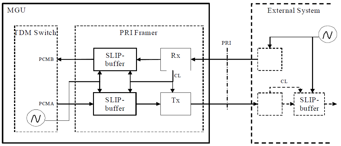
Transmit Slip Buffer
Each PRI interface contains "elastic" buffers (aka Slip buffers) in order to handle situations with different clock frequencies between MGU and an external telephony system. Slip buffers are always active in the receive path, but in the transmit path (towards the external system) it is optional to use.
In most scenarios when clock synchronization is properly administrated slip does not occur. However in some (temporary) scenarios, for instance when the DECT sync ring is used for PCM clock distribution there are certain situations when it is preferred to use a free running MGU oscillator as PCM sync "master". In such situations to avoid SLIP alarms on "external systems" an activation of a Slip buffer in the transmit path of the E1/T1 Framer of MGU is needed.
The activation is made by setting the TX_Slipbuffer parameter (see Table 4).
Layer 2 - Data Link Protocol
The PRI supports data link layer protocol ETS 300 125 (ITU-T ISDN user-network interface - Data link layer specification Q.921/I.441).
The PRI support point-to-point data link with non-automatic TEI assignment procedure.
Performance
The PRI signal capacity with an ISDN call rate of 5 calls/seconds generates less than 20% CPU load in net contribution from the ISDN traffic alone. The capacity figure is based on a ten Q.931 Layer 3 messages per call and one Layer 2 RR frame per message.