A Multi Layer Redundant Network Example
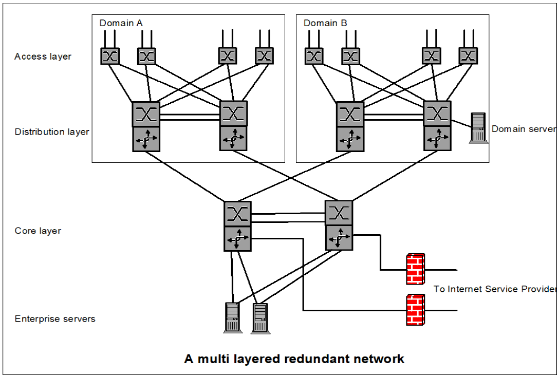
The picture above contains different layers:
Access layer
The users are connected to the access switches that all have redundant connections to the distribution layer. A user that needs redundant connection has to have redundant links to at least two physically separated access switches. The user access could if needed use different VLANs for different users groups.
Distribution layer
The distribution layer implements routing between users in different VLANs in the same domain. A domain could be a building or one floor in a building. The distribution layer has switching on level 2 and 3. It also has redundant links to the Core layer. This layer could contain servers that are needed in this domain only.
Core layer
This is the backbone of the enterprise network. Supporting switching and routing from level 2 to level 4. Core layer routes between different domains connect enterprise servers and have connection to the Internet Service Providers via firewalls.
Different physical locations such as buildings or a separate floor are implemented as a domain. The number of users is easy to scale by increased number of access switches. A new building would be added to the network as a new domain.