Loudness Ratings
The speech transmission components of terminal elements (analogue, digital, IP or cordless phones) are characterized by Send Loudness Rating (SLR) and Receive Loudness Rating (RLR) which contribute to the Overall Loudness Rating (OLR).
OLR of a connection is expressed as:
OLR = SLR + CLR + RLR
CLR, Circuit Loudness Rating, represents the sum of all analogue and digital losses between these telephone sets. An important loss factor of CLR includes level adjustment in a connection such as relative levels (dBr), loss plan and other loss/gain that might be introduced in the connection.
MiVoice MX-ONE Terminals
MX-ONE terminal elements comply with following standards.
Analogue phones
ETSI TBR 38 Public Switched Telephone Network (PSTN);
Digital and D4 IP phone
ETSI TBR 8 Integrated Services Digital Network (ISDN) Telephony 3,1 kHz teleservice;
D5 narrow band IP phone
ANSI/TIA-810-B Transmission Requirements for Narrowband Digital Telephones
|
SLR - Send Loudness Rating |
||
|---|---|---|
|
Analogue phone |
+3 +/- 4 dB Note 1 |
(ETSI TBR 38) |
|
Digital and IP phones |
+7 +/- 3.5 dB Note 2 |
(ETSI TBR 8) |
|
+8 +/- 4 dBNote2 |
(TIA 810) |
|
|
RLR - Receive Loudness Rating |
||
|---|---|---|
|
Analogue phone |
-8 +/- 4 dB Note 1 |
(ETSI TBR 38) |
|
Digital and IP phones |
+3 +/- 3.5 dB Note 2 |
(ETSI TBR 8) |
|
+2 +/- 4 dB Note 2 |
(TIA 810) |
|
Note 1: At maximum volume setting
Note 2: Normal volume setting
ITU-T Rec. G.107 specifies SLR = 8dB and RLR = 2 dB
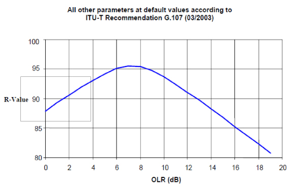
E-model rating of OLR:
The relation between the E-Model Rating R and the OLR of a connection is shown in the following figure. This graph, calculated with the E Model, is obtained when all other input parameters of the E-Model are set to their default values and OLR is the only impairment in the connection considered. The recommended value for the Overall Loudness Rating (OLR) for standard applications of 3.1 kHz handset telephony is 10 dB (ITU-T Recommendation G.111).
OLR Calculation:
As mentioned in Figure 1, the internationally recognized and recommended optimum OLR is 10 dB, CLR (circuit loudness rating) is therefore important parameter to be used to achieve a desirable port-to-port OLR value of 10 dB although the optimum value can not always be achieved in all connection types. Figure 2 illustrates computation of OLR in several simple connection cases.
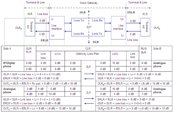
- It is assumed SLR = 8 dB, RLR = 2 dB for IP/Digital phone and SLR = 3 dB, RLR = -8 dB for analogue phone.
- CLR is the sum of all loss values Tx and Rx loss pads in port interfaces and loss values in the gateway. These Tx and Rx losses are 0 dB for digital extension ports. For analogue extension ports (short line), ETSI recommends, 5 dB loss in Tx direction (relative level Li) and 10 dB loss in Rx direction (relative level Lo).
- iSLR (IP SLR) is an equivalent SLR (ESLR) at the voice gateway-to-IP network connection point (also called ZLP, zero level point) and referred to IP send loudness rating at WAN interface. The iSLR is expected to be 8 dB as it obviously would be the case for IP/digital phone (SLR = 8 dB and all 0 dB loss till ZLP). This assumption, then, applies to analogue phone to determine proper relative level, i.e Li = 5 dB which results in iSLR = 8 dB (= 3 dB + 5 dB).
- ERLR - Equivalent Receive Loudness Rating, are RLR calculated at certain interface point of voice gateway. Here ERLR is defined at the edge of media gateway (interface ports of digital or analogue extension boards).
Loss plan of MiVoice MX-ONE media gateway
The OLR calculation shown in Figure 1 assumes that loss values are padded in the port interfaces (i.e. relative level, dBr) to achieve the optimum OLR value. The underlying idea (Reference [8]) is that the necessary loss values are standardized and embedded in overall level pan of interface ports so as to keep voice gateway loss-free.
However, the level plan of MX-ONE analogue interface ports is market dependent, i.e. relative levels are different for different market. For this reason, MX-ONE gateway needs to insert additional loss value unique to each market to obtain the optimum overall loudness rating.
The following table shows an example where Tx loss is 0 dB and Rx loss is 7 dB. It is equivalent to 0 dBr level point in transmit direction (port-to-ZLP) respective -7 dBr level point in receive direction (ZLP-to-port).
|
SLR |
CLR |
iSLR |
CLR |
RLR |
OLR |
|||
|---|---|---|---|---|---|---|---|---|
|
Analog phone |
TX pad |
Loss plan |
Loss plan |
RX pad |
||||
|
3dB |
0dB |
5dB (note 1) |
8 |
3dB |
7dB |
- 8dB |
10dB |
|
|
Note 1: iSLR value is expected to be 8 dB. Hence additional 5 dB loss value is added in loss plan (3 + 0 + 5 = 8). |
||||||||
|
Note 2: To achieve OLR 10 dB, additional 3 dB loss value is to be added (-8 + 7 + 3 = 2 dB) resulting in OLR = 8 dB (iSLR) + 2 dB = 10 dB. |
||||||||
Refer to the document MARKET CHARACTERISTICS for more details of market dependent loss and level plan, tone/line characteristics and any other market dependent data.
See also Harmonized Pan-European/North-American Loss and Level Plan between the Pan-European and the North American regions, ETSI published ES 202 020 (Ref [8]) and an equivalent ANSI/TIA-912-A (Ref [9]) published by the North American Telecommunications Industries Association