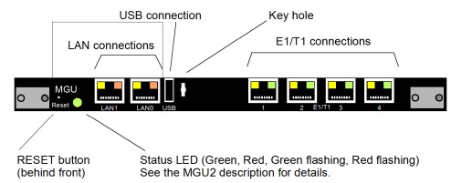
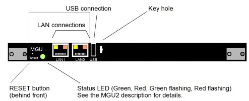
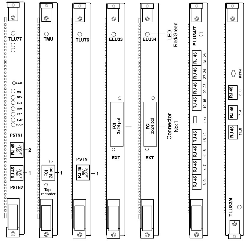
Connectors and LEDs on Board Fronts
This section describes the connectors and LEDs on the boards.
The indication of board status with dual color LED is:
-
Steady RED: The board is in passive state
-
Flashing RED: Error state
-
Alternating RED/GREEN: The board is starting up or is blocked.
-
Steady GREEN: The board is active.
-
Flashing GREEN: The board is active and is signaling.
DC/DC-, MGU-, TLU77- and ASU-boards deviate from above. See the figures below regarding how they differ.
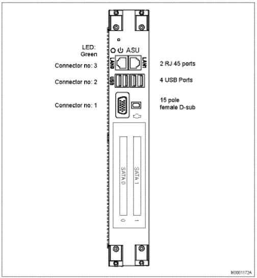
The SATA disks are located behind a cover. Two disks are used for RAID 1.
ROF137 6303/R1A-R3A
Yellow diode: -48 volt input voltage is supplied to the converter.
Green diode: +5 volt is present in the back plane.
Red flashing diode: Board is faulty. Investigate and replace the board if necessary.
No external alarm signal is provided in the front panel or in the back plane.
ROF137 6303/R5A and higher
The upper green LED diode: -48 volt input voltage is supplied to the converter.
The low green diode: +5 volt is present in the back plane.
ELU26 and TLU79 has equal fronts, only different printing.
TLU83/4 board has different connectors than TLU83/1 board. It have RJ45 connectors and uses standard network cables.
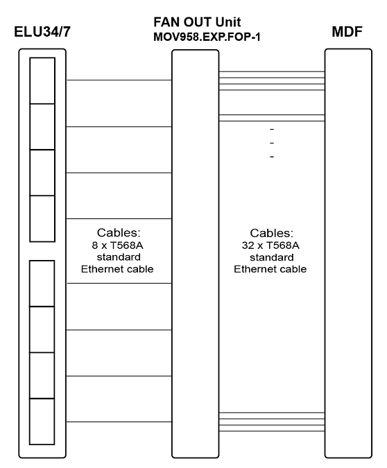
ELU34/7 board has different connectors than ELU34/6 board. It have RJ45 connectors and uses standard network cables.