Board Description
This chapter gives a high-level description of the Media Gateway Unit (MGU) board.
Board Layout and Front Connectors
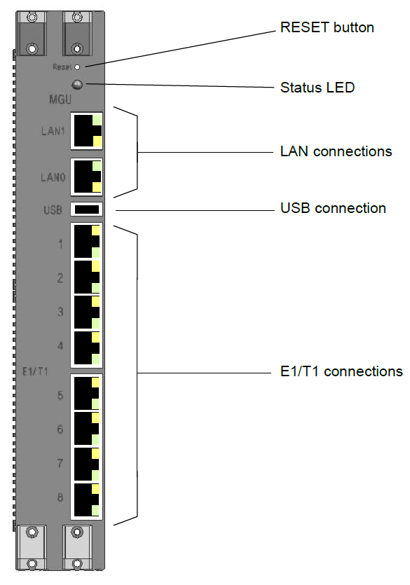
Figure below shows the MGU front and the external connectors in the front. For further description of these, refer to Interfaces.
Architecture
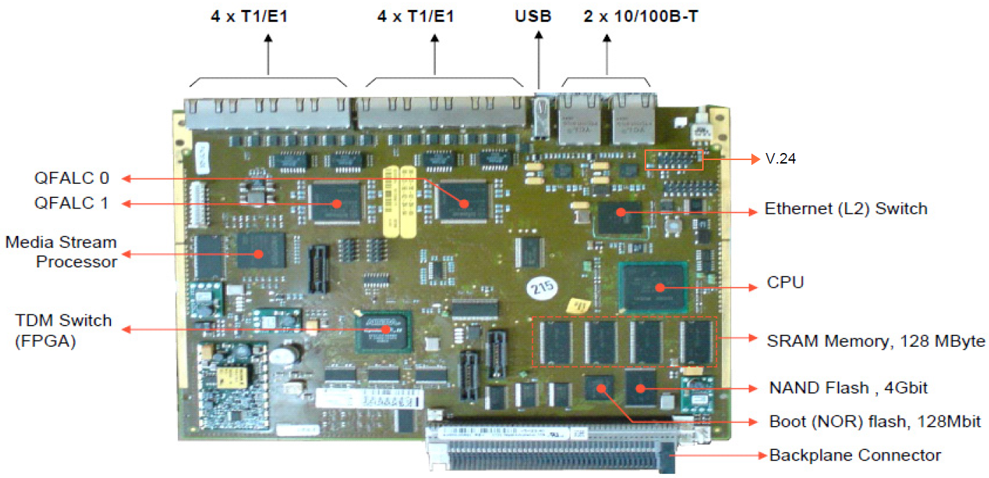
The MGU hardware architecture and its external interfaces (connectors) is outlined in figure below. The board has connectors in the front and to the backplane. The backplane is mainly the interface to other device boards, but also includes some alarm signals and power to the board.
Interfaces
- LAN0 and LAN1. Primary (LAN0) and Secondary (LAN1) LAN ports. These two ports provides support to connect to redundant networks. See also IP Network Redundancy for more information how to connect these.
- Device Board Interface (Backplane Interface). This is the interface towards all device boards. Up to 16 device boards can be accessed. It includes TDM buses (including frame sync input and output) and HDLC/UART signaling buses to all device boards.
- E1/T1. 8 Primary Rate Interface (PRI) for ISDN trunks, CAS trunks and CAS Extensions.
- Visual Indicators (front LED). The LED shows the operating status of the MGU board. There are also indicators on the LAN and E1/T1 connectors, see further Visual Indications.
- Reset button. The Reset button is connected to HW reset of the Device Processor (DP) and will immediately restart the board.
- USB. Management and service interface (linux console) which support USB to serial (V.24) bridge (USB serial dongle). A TSR 899 135/1 cable can be connected from this interface to for example a PC with terminal program. The terminal program shall be configured for 9600 baud, no parity, 1 stop bit to connect to this interface. Other USB serial dongles that uses a PL2303 chip might work as well.
Note: All management that can be done from the USB interface can also be done through SSH login.
V.24. The V.24 interface located on the PCB is mainly intended for debug purposes, but can be used as a "fall back" Management interface if USB access is not possible. Same terminal configuration as for USB applies. A TSR 43 297/1000 cable can be connected to this interface.